If you are really eager to start working with the PolyMesh plugin, you may want to skip this section and go to the next one, "Commands", but I advise you to read this section later on.
Polymeshes structure uses the half-edge mesh structure. There is not much to say about that, and if you want to know what an half-edge mesh structure is, you'll easily find the definition on the internet. The half edge structure is a subset of the winged-edge structure, which is used by Wings (hence the name).
What is more important to know to the user is how a polymesh is triangulated to a triangle mesh prior to rendering. Let me repeat this one more time: polymeshes are triangulated in order to be rendered.
Triangulation
Triangulation means that some decision must be taken on how to triangulate the mesh. For a given face, there are several possible cases which lead to different results.
The face is already a triangle. Not much to do, then, eh?
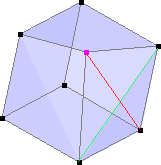
The face is a quad. Joining two opposite vertices along a diagonal does the job. However, there are two diagonals. Which one to choose, then? If the face is flat, then both choices yield the same result. If the face is not planar (which is generally the case), choosing one diagonal will lead to a convex shape, whereas choosing the other diagonal leads to a concave shape. Look at the distorted cube shown below. Non planar faces are broken into two triangles each. The default choice for triangulating a quad face is to end up with a convex volume, so the green diagonal is chosen.
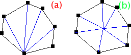
The face consists of more than four vertices. We will first suppose that the face is convex. The simplest way of triangulating the face is to choose an arbitrary vertex and then draw edges to each other vertex, as shown on the left part (a) of the next figure. This scheme has an important drawback: it arbitrarily breaks the symmetry of the face, giving a single vertex a different role than every other vertex of the face. The other possibility is using scheme (b): edges are drawn from the face center up to every vertex of the face boundary. However, this design adds a vertex at the center of the face.
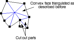
The face consists of more than four vertices and it is not convex. All the non convex part are triangulated using the so called "ear-cutting" algorithm. All the concave parts that stick out of the face inner part are cut into triangles (see figure below). The convex center part of the face is then triangulated as explained above, be it a quad or a general convex polygonal face.
Thus, any face that has more than three vertices (triangle) introduces new edges, and any concave face that has more than four vertices introduces a new vertex. New edges have a smoothness of 1.
Duck bills
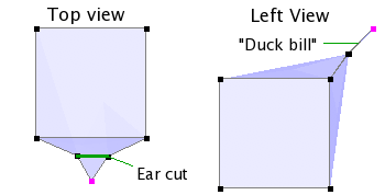
Triangulation design as previously described can lead to an artifact which I call "duck bills" for lack of a better description. This happens when two adjacent polygonal faces share two triangular faces which are made of the same points but have opposite normals. Have a look at the following figure. Two adjacent polygonal faces have 7 vertices each, sharing edges which describe concave parts of each face. According to the ear cutting process for triangulating convex parts of a face, the triangle that makes up the concave part of each face is cut for both faces. As a result, these two faces share the same triangle, only its normals differs from one face to another (opposite signs). Whereas this mesh structure is legal as far as the PolyMesh is concerned, it cannot be smoothed by an underlying triangle mesh. So if you happen to edit a polymesh with smoothing on and suddenly the smoothed preview switches to unsmoothed, a good guess is that there is a duck bill somewhere.
Texturing
As for texturing, texture parameters are inferred from their values at the boundary of the face. Texture parameters can be defined per face or per vertex. Unlike the triangular mesh, texture parameters cannot be defined per face-per vertex. In case texture parameters are defined per face, adding a vertex at center doesn't affect texture mapping. If texture parameters are defined per vertex, the value for the vertex added at face center corresponds to the mean value of boundary vertices.


