Edit Menu
Copy mesh / Paste mesh: This command copies a mesh as a whole which can be pasted in any other PolyMesh editor window. As a result, the polymesh will consist of two disjointed meshes. It is intended that these two meshes are unified later on, presumably using . The pasted mesh inherits texture and material parameters from the mesh it has been pasted in. Parameters are set to a default value and any texture parameters pertaining to the pasted mesh are lost. The polymesh editor clipboard is independant form AoI main clipboard.
View along normal to current selection: As the item title says, this command rotates the view (not the object) so as to align the normal to the selection along the viewing direction.
Scale selection. Scales the whole selection around its center using the slider/text field at the right of the window.
Mesh Menu
Smoothing Method. Mesh smoothness can be only set to none, shaded or approximated. Approximation smoothing uses Catmull-Clark smoothing with variable edge smoothness. Smoothing levels specify the number of subdivisions to be applied for interactive views and renders. The greater the number, the finer the mesh. A high number of subdivisions leads to high memory usage and long computations. For this reason, the subdivision levels are limited to 6. The default numbers are good guesses. An additional trimesh smoothing is carrried out after Catmull-Clark subdivision when rendering, so you don't need to bother whether the subdivision level is high enough. Since this level greatly affect editor responsiveness in interactive views, the interactive level can be decreased/increased using the X and C keys (provided you didn't change the Keystrokes shortcuts). The S key toggles the view between smoothed or unsmoothed (this does not affect the real mesh smoothing status). Interactive and rendering levels can also be set using the two spinners at the bottom of the editing window.
Currently implemented smoothing algorithm make it possible to specify a smoothness coefficient ranging form 0 to 1 to each edge. [0-1] values for vertex smoothness is not possible, however any vertex can be specified as a corner, i.e. sharp. Corners/edges smoothness can be set using relevant widgets at the bottom of the editor window (depending on edit mode).
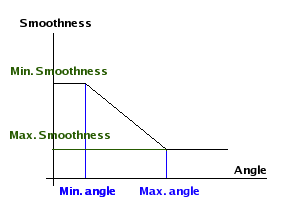
Auto Smoothness. Edge smoothness parameters are calculated according to the angle between the two faces that neighbor and edge. The dialog asks for a minimum angle, maximum angle, minimum smoothness and maximum smoothness. If the angle between two faces is lwoer than Min Angle, then the smoothness of the edge is set to Min Smoothness. If the angle is between the Min Angle and the Max angle, then the smoothness is computed as a linear interpolation between Min Smoothness and Max Smoothness. If the angle is above Max Angle, then the edge smoothness is set to Max Smoothness. Min and max smoothness are convenient denominations, it generally happens that the value for Min Smoothness is greater than Max Smoothness for practical purposes. An example of smoothness as a function of angle is plotted in the figure below.
These rules are applied to the triangulated mesh rather than the polymesh. This allows to compute smoothness values for edges added inside polymesh faces which consist of more than 3 vertices. If the Auto Smoothness feature is disabled, polymesh edges smoothness will be set to values close or equal to those of the triangulated mesh. Additional edges smoothness will have to be setup using face properties. So it may happen a mesh shape changes in a more or less pronounced way upon disabling auto smoothness feature.
Smooth mesh. Smooths the whole mesh according to the Catmull-Clark algorithm. The smoothed mesh always end up a quad mesh due to the nature of the algorithm, however any kind of mesh can be smoothed (triangular, polygonal)
Subdivide mesh. Subdivides the whole mesh in a manner similar to "Smooth mesh", however the mesh is not smoothed. Only new points are added. As for the smoothed mesh, the resulting mesh is a quad mesh.
Thicken mesh. This command is available only if the edited mesh is opened. In this case, selecting the mesh command will thicken the mesh by an amount specifed using the slider/text field on the right side of the window. The thickening may happen along a given direction or the selection normal.
Mirror modelling. It is possible to set up mirrors in the editor so that only half to one eighth of the mesh has to be edited. The mirrors can be set in the XY, YZ and/or XZ plane. When this feature is enabled, any face that lies on the mirror plane is a "mirror spot". A face is said to be lying on the mirror if the relevant coordinate of all its vertices is equal to zero. For example, a face is a mirror source on the YZ plane if all the x coordiantes of its vertices are 0. If several neighboring faces have all of their vertices lying on the plane, then the whole group (region) acts as a mirror source. It is possible to mirror the mesh using several disjointed groups/faces. Mirrors are cumulative. For example, if all three mirrors are used, then one eighth of the mesh is modeled. Mirrors can be removed through unchecking the relevant menu items. If you want to keep the mirrored mesh as a result, then use the command. A dialog will then allow you to keep the resulting mirrored mesh. Mirror can be toggled on/off in the view using the N key. As for the S smoothing toggle, this does not affect the true mesh mirroring status.
Mirror whole mesh. This command replaces the mesh by its mirrored version. Mirror can be any of the three XY, YZ and XZ plane. Normals are inverted in the process.
Invert normals. Inverts all normals to the faces of the mesh. You don't normally need to do that (commands like Mirror take care of inverting normals). However, this commend may be used when a faulty model has been imported.
Check and repair mesh. This command checks the mesh for invalid data. This is mainly useful for debugging purposes, but it also might be helpful to pinpoint what the problem is if you suspect a bug in the PolyMehs plugin. If possible, some basic corrections will be applied to the mesh in case it turns out to be faulty.
Save as Model. This command exports the current mesh in a format suitable for polymesh templates that can be recalled at polymesh creation time in AoI main window. The template is saved in the PolyMeshTemplates subfolder of the Plugins folder.
Vertex Menu
Connect. This command connects selected vertices with edges. The following rules are applied in order to find out which vertices should be connected:
Connected vertices must belong to the same face;
When connections can be carried out in several ways (ambiguity) then the connections that lead to the most perfect quads are established;
No triangular face shall be created (preserving quad mesh as much as possible) unless only two vertices are selected, in which case the user's action prevail.
Move along (Normal, X, Y, Z). Constrained movement along one of these directions. Amplitude is entered using the slider/text field at the right of the window. See PolyMesh Editor Window features description.
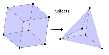
Collapse. All edges coming form the selected vertex (vertices) are collapsed. In other words, all vertices sharing an edge with a selected vertex are move to the location of the selected vertex. See figure below.
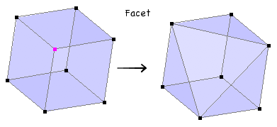
Facet. Selected vertex (vertices) is deleted and replaced by the face built on its neighbor vertices. See figure below.
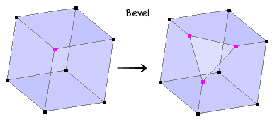
Bevel. Bevels the selected vertices exactly like Facet does, except amplitude is controlled using the slider/text field at the right of the window. See figure below.
Inflate. This command is available if four or more points are selected. A mean sphere is computed, its center being the selection center and its radius the mean distance between selection center and each selected vertex. Varying the amplitude brings vertices from initial locations (0) to the mean sphere (1) along the radii.
Spherical. This command is available if four or more points are selected. The closest sphere to selection is computed (which yields generally a sphere quite different than the mean sphere computed by the Inflate command). Varying the amplitude brings vertices from initial locations (0) to the computed sphere (1) along the radii.
Flattens. This command is available if four or more points are selected. The closest plane to selection is computed. Varying the amplitude brings vertices from initial locations (0) to closest plane (1) along the normal to the plane.
Select Boundaries. If one or more vertex is selected, then every vertex belonging to a boundary crossing the initially selected vertices becomes selected. If no vertex is initially selected, then every vertex crossing by a boundary (no matter which one) becomes selected.
Close Boundary. Each boundary crossing a selected vertex is replaced by a face. It is not necessary that the whole boundary is selected.
Join Boundaries. This command joins two boundaries much like the triangle mesh editor does. Two and only two vertices must be selected, one for each boundary to join. An edge is created between these two vertices and then other vertices of the two boundaries are connected using the rules of the Connect command. I f one boundary has more vertices than the other, then triangular faces will be created. Otherwise, this command only creates quad faces.
Edge Menu
Divide. Divides selected edges in n equal parts. Since this command is used generally to connect vertices after being selected, the editor enters point selection mode after this command has been executed.
Move along. Same as the Vertex menu command.
Extrude. Extrudes individual boundary edges along the chosen direction. Extrusion amplitude is set using the slider/text field. Please note that only boundary edges can be extruded.
Extrude Region. Extrudes groups of edges along the chosen direction. Extrusion amplitude is set using the slider/text field. As for extrude, only boundary edges can be extruded.
Collapse. Brings together the two vertices of every selected edge.
Merge. Merges consecutive selected edges into a single edge.
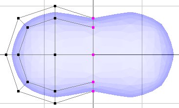
Bevel. Bevels selected edges. Use the slider/text field at the right of the window to select bevel amplitude. The editor does not impose a maximum value so it is possible to end up with edges beveled further than their bordering faces would allow (b). Just before that point, faces that borders the edge colllapse, i.e they have a null area. The PolyMesh can detect such situations and remove faces which have an area too small to be meaningful (c).
Select edge loop. Starting with selected edge(s), this command tries to find a loop of edges going back to originally selected edge(s).
Select edge ring. Same as above, except selected edges are perpendicular to the edge loops.
Insert loops. This command may be to used to quickly insert an edge loop in between two loops. Select one (or several) edge(s) and then select the Select edge strip command. Check that strips are properly selected (since on some occasions the loop selection is not carried out properly, this selection is not automatic). Then select the Insert loops command. The position of the inserted loop(s) can then be varied using the slider.
Select boundaries/Close boundary. These commands work the same wy than the corresponding Vertex menu commands.
Find similar... Given a selection of edges, this commands selects other edges similar to the ones selected. In this case, similar means having the same length. Tolerance with respect to length for similitude check can be specified in the Find Similar... dialog.
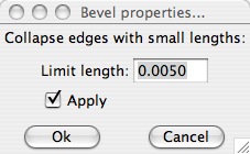
Bevel properties. When applying a certain amount a beveling, it sometimes happens that vertices overlap. In this case, it is generally wished that the edges connecting overlapping vertices are collapsed. This behavior is not automatic but it can nonetheless be achieved setting two parameters. The Bevel properties command brings the window shown below. If you wish to collapse small edges during bevel in order to avoid overlapping vertices, check the Apply checkbox. The Limit length value allows to tune the limit under which edges are collapsed. Caution: every edge of the mesh is affected, not just those being beveled. Beware of deleting small edges that do not take part in the bevel process.
Face Menu
Move along. Same as the Vertex menu command.
Extrude faces. Extrudes individual faces along the chosen direction. Extrusion amplitude is set using the slider/text field.
Extrude Region. Extrudes groups of faces along the chosen direction. Extrusion amplitude is set using the slider/text field.
Smooth faces. Selected faces are smoothed according to the Catmull-Clark algorithm. Neighbor faces are partially subdivided in order to accomodate subdivision resulting from smoothing.
Subdivide faces. Selected faces are subdivided in the same way as the Catmull-Clark algorithm does. However, no smoothing occurs. As for smoothing, neighbor faces are partially subdivided in order to accomodate subdivision.
Collapse. Selected faces or groups of selected faces are replaced by a single vertex. To do: optimize vertex location when considering a group of several faces.
Merge. Merges several faces into a single face.
Triangulate faces. Selected faces are replaced by triangulated faces. Triangulation is carried out the same way as for calculating a rendering mesh, so this process doesn't change mesh surface whatsoever. Triangulating faces is useful if they happen to have a more than reasonable numbre of vertices and prove difficult to work this.
Find Similar... This command has the same purpose as the Find Similar... for edge edit mode. However, parameters for deciding when a face is similar to antoher one are a bit more comprehensive. You can specify a tolerance on face orientation : 0.01 (default) means all faces having the same normal as the already selected ones whereas 180 degrees means face orientation doesn't matter. Faces shapes (angles) allows to select faces having the same shape as the currently selected ones but size doesn't matter since only angles between faces edges are compared. Faces shapes (distances) constrains the faces sizes as well. Given this set of parameters the face mode Find Similar... is a very powerful tool to select faces akin in any aspect.
Preferences
Reload Polymesh Keystrokes... When it is loaded for the first time, the Polymesh plugin adds its own keystrokes to the AoI keystroke pool. Keystrokes aren't modified hereafter even when updates are released. The point is that you might have changed keystrokes contents for a reason or another. However, some scripts associated to the keystrokes might become obsolete and indeed raise errors. In this case, it is advised to reload the keystrokes anew. Existing keytrokes associated to PME will be deleted and reloaded using the latest keystrokes list shipped within the plusing file.
Edit Keystrokes... This command makes it possible to edit keystrokes directly from the PM editor window. Resulting dialog is equivalent to the keystrokes edit panel available using AoI Prefs menu item.
